


![]()

Datasheet
Test Report
2D drawing
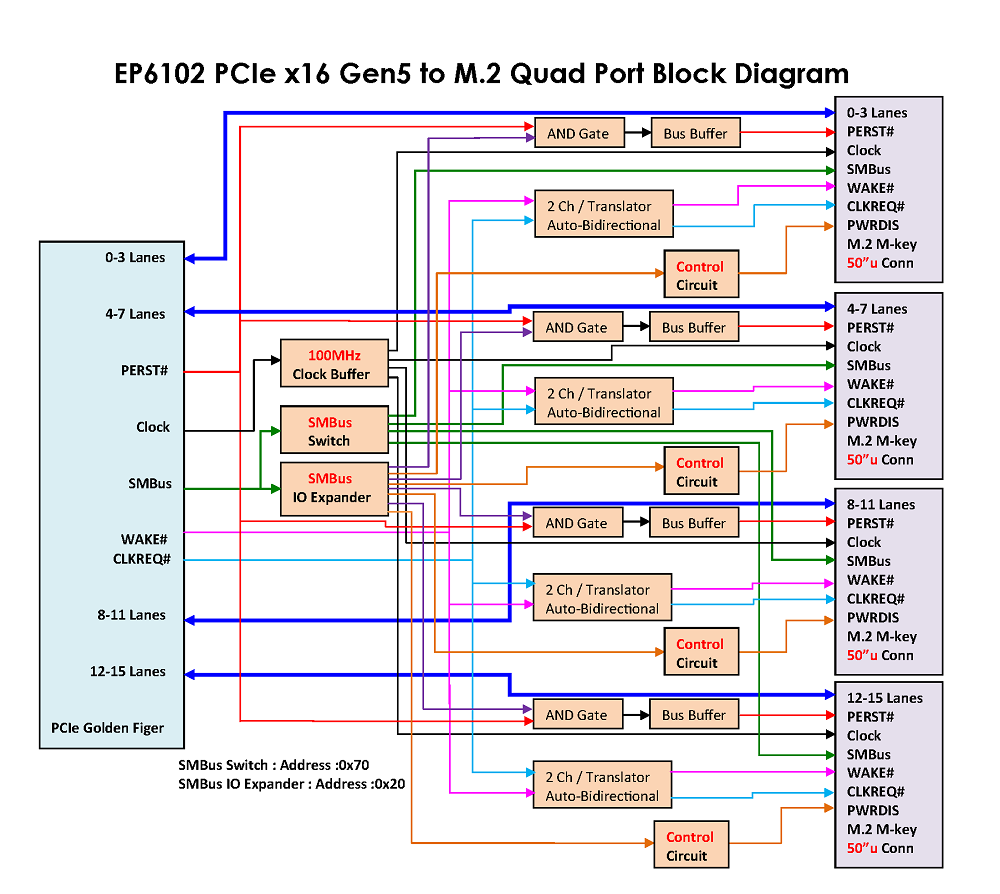
Block Diagram
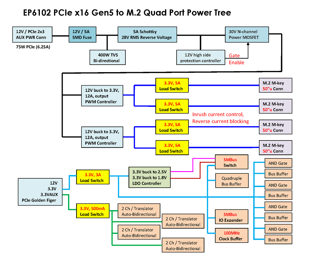
Power Tree
![]()
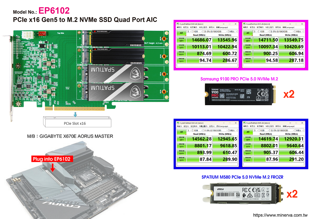
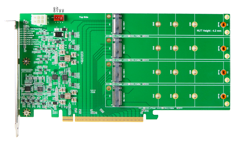
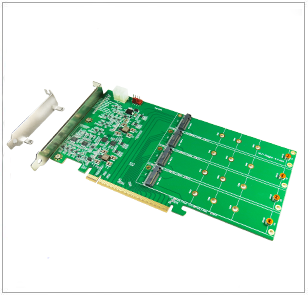
- M.2 quad port to PCIe x16 Gen5 convert
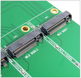
- Built-in four M.2 M-key connector with 50μ gold-plated contacts
- 12V to 3.3V PWM synchronous buck converter for M.2 connector CN1, CN2
- ◆ Support 12-A Continuous current
- ◆ The undervoltage lockout (UVLO) circuit monitors
- 12V to 3.3V PWM synchronous buck converter for M.2 connector CN3, CN4
- ◆ Support 12-A Continuous current
- ◆ The undervoltage lockout (UVLO) circuit monitors
- Each M.2 connector input is built-in 3.3V Load Swtich
- ◆ 5-A Maximum Continuous Switch Current
- ◆ Adjustable Undervoltage Lockout Threshold (UVLO)
- Supports PCIe PERST# for OOB(out of band) management to remote M.2 Reset
- Built- in PCIe WAKE# bidirectional voltage-level translator for Open-Drain output to be used more PCB trace lengths and more longer cable
- Built- in PCIe CLKREQ# bidirectional voltage-level translator for Open-Drain output to be used more PCB trace lengths and more longer cable
- Built- in SMBus Switch for each M.2 1.8V SMBus port, Address: 0x70(7 bits)
- Built- in SMBus I/O Expander for each M.2 PWRDIS signals control, Address: 0x20(7 bits)
- LED 1 Red LED on indicates input 12V Power error
- LED 2 Green LED on indicates 1.8V Power ready
- LED 3 Red OFF indicates WAKE# Normal (Function intentionally inverted)
- LED 4 Red OFF indicates CLKREQ#Normal (Function intentionally inverted)
- LED 5 Red OFF indicates PERST#Normal (Function intentionally inverted)
- LED 6 Green LED on indicates 3.3V Power ready
- LED 7 Green LED on indicates 3.3VAUX Power ready
- LED 8 Green LED on indicates AIC present
- LED 11 Green LED on indicates M.2/CN1 3.3V Power ready
- LED 12 Red LED flash indicates M.2/CN1 Active
- LED 21 Green LED on indicates M.2/CN2 3.3V Power ready
- LED 22 Red LED flash indicates M.2/CN2 Active
- LED 31 Green LED on indicates M.2/CN3 3.3V Power ready
- LED 32 Red LED flash indicates M.2/CN3 Active
- LED 41 Green LED on indicates M.2/CN43.3V Power ready
- LED 42 Red LED flash indicates M.2/CN4 Active